FireProtect 2 AC (Heat/Smoke/CO) Jeweller is a wireless mains-powered fire detector with a backup battery and a built-in siren. Designed for indoor installation. Detects smoke, temperature rise, and dangerous CO (carbon monoxide) level.
The fire detector is also available without an external power supply in two modifications: FireProtect 2 SB (Heat/Smoke/CO) with sealed batteries that last 10 years, and FireProtect 2 RB (Heat/Smoke/CO) with replaceable batteries that last up to 7 years.
The detector operates as part of the Ajax system, communicating with the hub via the Jeweller secure radio protocol. The hub communication range is up to 1,700 m without obstacles.
Versions of the detector with other sensor combinations are also available. All Ajax fire detectors are available here.
CableTrunk is available for the FireProtect 2 AC detectors for convenient cable routing. It allows you to neatly route the fire detector’s power cable from the standard cable trunking. Use CableTrunk when it is impossible to route the power cable from the back of the detector and hide it inside walls or ceiling.
Functional elements
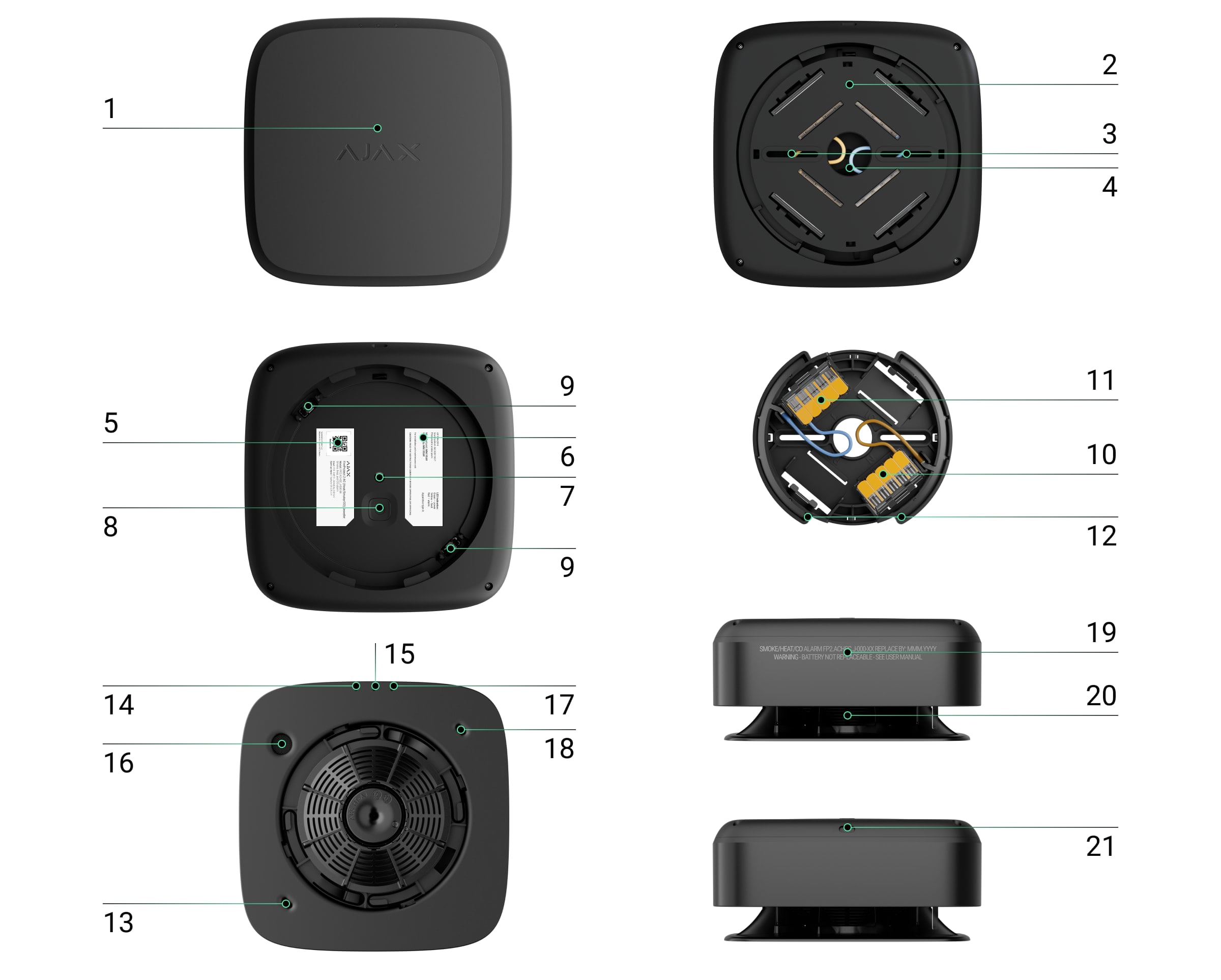
The front panel of the detector with a Test/Mute button. To activate the button, press the center of the panel.
SmartBracket mounting panel with protective cover. To remove the panel, insert a screwdriver into the appropriate hole (functional element 21) and turn SmartBracket counterclockwise.
Holes to attach SmartBracket to the surface.
A hole to run the wires.
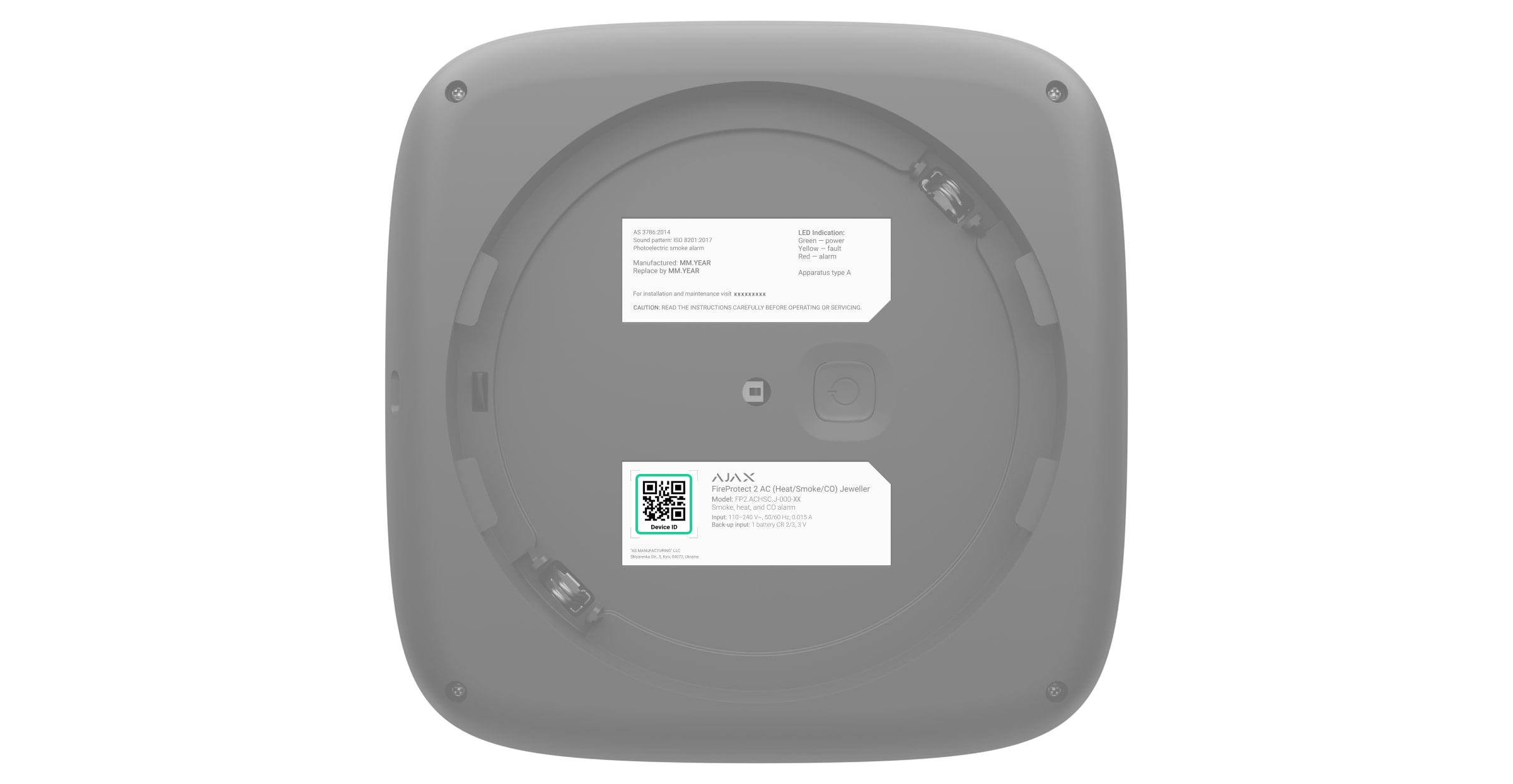
Device QR code and ID (serial number). It is used to add the detector to the Ajax system.
Detector certification information.
Tamper button. Triggers when an attempt is made to detach the detector from the surface or remove it from the mounting panel.
Power button.
Detector’s contacts.
Power supply phase (L) connection terminals WAGO 221.
Power supply neutral (N) connection terminals WAGO 221.
Contacts on the SmartBracket mounting panel.
First thermistor. Detects dangerous temperatures.
Green LED indicator.
Yellow LED indicator.
Siren.
Red LED indicator.
Second thermistor. Detects dangerous temperatures.
Information about the detector’s end of life date.
Smoke chamber lid.
Hole to insert a screwdriver.
The smoke chamber lid can be removed when the enclosure is disassembled completely. The system identifies this event as a malfunction, and the detector reacts with an audible signal. Users and the security company receive a malfunction notification.
Compatible hubs and range extenders
The detector is compatible only with Ajax hubs with the firmware OS Malevich 2.18 and later. Hub (4G) Jeweller must have OS Malevich 2.28 or later to support this detector.
The detector also can work without a hub.
Operating principle

FireProtect 2 AC (Heat/Smoke/CO) Jeweller is a wireless fire detector designed for indoor installation. It can operate from a 110-240 V~, 50/60 Hz power supply, and has a built-in backup battery.
The Battery Life Optimization feature must be enabled to ensure such a lifetime for a built-in backup battery.
The detector is equipped with a siren (piezoelectric buzzer) for audible notification of alarms and events with a volume of up to 85 dB (at a distance of 3 m from the detector). The detector is always active and reacts to a fire 24/7, regardless of the system’s security mode.
A smoke/temperature rise alarm can be easily distinguished from a high CO level alarm due to different audible and LED indications. Learn more about the types of indication of the detector’s alarms and events in the LED Indication section of this manual.
FireProtect 2 is protected by two tamper buttons. The first tamper informs if someone tries to remove the detector from the SmartBracket mounting panel. The detector responds with LED indication. The users receive notifications via Ajax apps while the monitoring station processes the alarm. The second tamper notifies on the removal of the smoke chamber lid, which is located under the front panel of the detector.
Ajax automation devices respond to FireProtect 2 alarms and perform user-defined actions using automation scenarios. For example, the WallSwitch relay can turn off the ventilation system and turn on emergency lighting when an alarm occurs.
Smoke sensor
FireProtect 2 detects smoke with a bispectral optical sensor. Inside the smoke chamber, the sensor has blue and infrared LEDs which emit light at different wavelengths. This technology allows the detector to determine the size of the volatile particles inside the chamber and respond to smoke.
The smoke chamber in FireProtect 2 is protected from dust, dirt, and insects. Even if dust gets inside and settles, this does not threaten or impair fire detection. The optical system is designed to prevent non-volatile particles from simultaneously getting within the field of blue and infrared LEDs. So that situation does not cause a false alarm.
The HazeFlow 2 software algorithm also protects against false alarms. When an alarm is detected, the algorithm additionally processes the data received from the detector and confirms the alarm.
Heat sensor
Two built-in class A1R thermistors detect a rapid rise and exceeding the temperature threshold in FireProtect 2. Such thermistors notify of alarms when a rapid temperature rise or static temperature is detected in the range of +54°C to +65°C.
FireProtect 2 reports that the temperature threshold has been exceeded as soon as its value exceeds +64°C. The detector reports a rapid temperature rise if the indicator increases by 10°C within one minute. If the temperature indicator rises sharply by 20°C or more, the detector alerts immediately.
CO (carbon monoxide) sensor
FireProtect 2 has a chemical sensor which detects dangerous levels of carbon monoxide. The operation principle of the sensor is based on a chemical reaction. There is an electrolyte bath inside the sensor. When a specific level of carbon monoxide is reached, a chemical reaction is triggered. The detector reads this event and transforms it into an alarm.
The detector raises an alarm if the CO level reaches:
50 ppm (0.005%) and above — within 90 minutes max.
100 ppm (0.01%) and above — within 40 minutes max.
300 ppm (0.03%) and above — within 3 minutes max.
A CO concentration of 400 ppm (0.04%) for three hours is life-threatening. The detector stops warning of a dangerous carbon monoxide level as soon as the concentration drops to 40 ppm (0.004%).
Test/Mute button
Тo activate the Test/Mute button, press lightly on the centre of the front panel with your hand. Use a suitable item (mop handle) if you can’t reach up the detector with your hand. Test/Mute is a mechanical button placed under the front panel of the detector.
The button performs several functions:
In normal mode, it starts the detector self-test.
When operating in a network of fire detectors that propagate an interconnected fire alarm without a hub, it starts a network coverage area testing.
In case of an alarm, it mutes the detector alarm or Interconnected Alarm of all fire detectors in the system for 10 minutes.
In case of a fault, low battery level, or end of life, it mutes the sound and LED indication for 12 hours.
To run the self-test or network coverage area testing, wait at least 3 minutes after turning on the detector. Use any remote silencing feature (e.g., via Ajax app) only in the line of sight of the CO sensor.
Interconnected Fire Detectors Alarm*
All FireProtect 2 AC detectors in the system can synchronously notify about the fire alarm. There are two ways: primary and fallback (both work in parallel).
In case of danger, the initiating detector sends a fire alarm to the hub. The hub initiates the primary interconnect: all fire detectors will activate the built-in sirens in 20 seconds. Meanwhile, the initiating detector activates the fallback interconnection, directly sending the alarm to other fire detectors. Even if the connection with the hub is lost, raising the interconnected fire alarm takes a minute.
The fallback interconnection functionality is available for hubs with OS Malevich 2.19 and later. Hub (4G) Jeweller must have OS Malevich 2.28 or later to support the fallback interconnection.
The FireProtect 2 detectors have different sound and LED indications of alarm types to make it easier for users to distinguish between them. In the case of interconnected alarm, all FireProtect 2 detectors indicate exactly the alarm type detected by the initiating detector.
How to set Interconnected Fire Detectors Alarm
How to mute Interconnected Fire Detectors Alarm
*To comply with AS3786:2014, EN 14604, and EN 50291 standards, enable the fallback interconnection in the hub settings.
Sending events to the monitoring station
An Ajax system can transmit alarms to both PRO Desktop monitoring app and the CMS in the formats of SurGard (Contact ID), SIA (DC-09), ADEMCO 685, and other protocols.
FireProtect 2 AC (Heat/Smoke/CO) can transmit the following events:
Smoke alarm/restoration.
Alarm caused by a rapid rise in temperature. Restoration.
Alarm caused by exceeding the threshold temperature. Restoration.
Alarm caused by exceeding CO (carbon monoxide) concentration in the air. Restoration.
Tamper alarm and restoration.
Loss/restoration of connection with the hub.
Permanent deactivation/activation of the detector.
When an alarm is received, the operator at the security company’s CMS knows what happened and precisely where to dispatch a rapid response team. The addressability of Ajax devices allows sending events to PRO Desktop or the CMS, including the device type, its name, security group, and virtual room. Note that the list of transmitted parameters may vary depending on the CMS type and its communication protocol.
Check the device ID and the loop (zone) number in the device States via the app.
Adding to the system
Before adding a device
Install the Ajax app.
Log in to your account or create a new one.
Select a space or create a new one.
The space functionality is available for apps of such versions or later:
Ajax Security System 3.0 for iOS;
Ajax Security System 3.0 for Android;
Ajax PRO: Tool for Engineers 2.0 for iOS;
Ajax PRO: Tool for Engineers 2.0 for Android;
Ajax PRO Desktop 4.0 for macOS;
Ajax PRO Desktop 4.0 for Windows.
Add at least one virtual room.
Add a compatible hub to the space. Ensure the hub is switched on and has internet access via Ethernet, Wi-Fi, and/or mobile network.
Ensure the space is disarmed, and the hub is not starting an update by checking statuses in the Ajax app.
Only a PRO or a space admin with the rights to configure the system can add a device to the hub.
Types of accounts and their rights
The detector must be within the coverage area of the hub radio network. To operate via the radio signal range extender, first pair the detector with the hub and then with the range extender. You can do this in the range extender settings in the Ajax app.
How to pair FireProtect 2 with a hub
Open the Ajax app and select the hub to add the detector.
Go to the Devices
tab and click Add device.
Name the detector, then scan or manually input the QR code (located on the detector and the package box). Next, select a room and a group (if Group Mode is enabled).
Click Add.
If you’ve reached the maximum number of devices the hub can support (depending on the hub model), you’ll receive a notification when attempting to add another device.
Turn on the detector by holding the power button for 3 seconds. The hub connection request is sent only if the detector is enabled. If the detector fails to pair with the hub, try again in 5 seconds.
The hub and the device operating at different radio frequencies are incompatible. The device frequency range may vary by region. We recommend purchasing and using Ajax devices in the same region. You can verify the range of operating radio frequencies with the technical support service.
Once added, FireProtect 2 appears in the hub device list in the Ajax app. Device status update depends on the ping interval set in the Jeweller or Jeweller/Fibra settings. The default value is 36 seconds.
FireProtect 2 works with one hub. When connected to a new hub, the device stops sending events to the previous one. Adding the detector to a new hub does not automatically remove it from the device list of the previous hub. This must be done through the Ajax app.
Autonomous operation mode
FireProtect 2 detectors can be used autonomously without connecting to an Ajax hub. In this case, the detector notifies of fire, smoke, or dangerous CO level with only a built-in siren and LED indication. Users don’t receive notifications on any Ajax apps, including Ajax Translator, or PRO Desktop.
How to configure the autonomous operation mode
Indication

LEDs and the built-in siren of the detector can report alarms as well as certain states of the detector.
LED indication | Sound indication | Event | Notes |
The red LED flashes continuously. | The siren sounds in time with the LED indication. | Alarm by:
| The detector stops alarming as soon as its sources are eliminated. |
The red LED flashes 3 times every 3 seconds. | The siren beeps in time with the LED indication. | Alarm by dangerous CO (carbon monoxide) level. | The detector will stop alarming as soon as the CO level drops below 50 ppm. You can also mute the alarm by pressing the Test/Mute button or in the Ajax app. The alarm cannot be muted if the CO level exceeds 300 ppm. The LED and sound indications resume if the source of the alarm is still present after the muting timer (10 minutes) has expired. |
No. | Short, low tone beep. | Prohibition on alarm muting. | The sound is played after pressing the Test/Mute button. The alarm cannot be muted if the CO level exceeds 300 ppm. |
The red LED flashes every 4 seconds. | No. | Muted alarm. | The detector stops alarming as soon as its source is eliminated. |
The red LED flashes 2 times in a row. | No. | Restore after alarm. | If the source of the alarm is removed, the detector is restored automatically. |
The yellow LED lights up for 1 second. | No. | Tamper alarm. The detector is removed from the SmartBracket mounting panel. | |
The green LED lights up for 1 second. | No. | The detector is installed on the SmartBracket mounting panel. | Turns on when the tamper is triggered. |
Green, yellow, and red LEDs light up in turn, then go off. | No. | Turning the detector on. | To turn on the detector, hold the power button for 1 second. |
Green, yellow, and red LEDs light up at the same time, then go off in reverse order. | No. | Turning the detector off. | To turn off the detector, hold the power button for 2 seconds. |
The green LED is permanently on. | No. | Connection to the hub in progress. | The indication turns off after the detector is connected to the hub. |
The green LED flashes 6 times in a row. | No. | The detector has been removed from the hub. | The indication turns on when the detector receives information that it has been removed from the hub. |
The green LED is constantly on. | No. | The detector operates from an external power supply. | The indication is present when the detector is on and the tamper status is OK (the detector is installed on the SmartBracket mounting panel). There is no indication when the detector switches to the Jeweller Signal Strength Test mode. |
The green LED flashes once per minute. | No. | The detector is powered by a backup battery. The detector does not have an external power supply. | The indication is present when the detector is on and the tamper status is OK (the detector is installed on the SmartBracket mounting panel). There is no indication when the detector switches to the Jeweller Signal Strength Test mode. |
The yellow LED flashes 2 times in a row every minute. | The siren beeps in time with the LED indication every minute. | Malfunction detected. | All malfunctions are displayed in the detector states in Ajax apps. Fields with malfunctions are highlighted in red. If the detector needs to be repaired, contact our Technical Support. |
The yellow LED flashes once per minute. | The siren beeps in time with the LED indication once per minute. | Low backup battery level. | The detector should be replaced with a new one after the batteries are discharged. |
The yellow LED constantly flashes. | No. | The backup battery is completely discharged. | The detector must be replaced with a new one after the batteries are discharged. |
The red LED flashes 5 times during the smoke chamber test. Then flashes 3 more times but slower during the CO sensor test. | The siren beeps 5 times during the smoke chamber test. Then it makes 3 longer beeps during the CO sensor test. | Performing a self-test. | The test can be started by pressing the Test/Mute button or in the detector settings in the Ajax app. In CO-free versions, only the smoke chamber is tested. |
The yellow LED flashes 3 times in a row every minute. | The siren beeps 3 times every minute. | The device service life has expired. | The device has operated for more than 10 years. The sensitivity of its sensors may have decreased. We recommend replacing this detector with a new one. |
Green, yellow, and red LEDs flash at the same time. | No. | The detector decides in which role it will switch to the pairing mode: master or slave. | The indication turns on when the power button is pressed 3 times on the detector that is switched on and not added to any hub. The indication lasts up to 10 seconds. The detector switches to the pairing mode to set up a network of detectors that can propagate an interconnected fire alarm without the hub. |
Green, yellow, and red LEDs light up and go off in turn. Then, light up and go out in reverse order. | No. | The detector becomes a master after switching to the pairing mode. | The indication turns on when the detector chooses its role after switching to the pairing mode without the hub. It turns off when the network of detectors is formed. |
The green LED flashes every 2 seconds. | No. | The detector becomes a slave after switching to the pairing mode. | The indication turns on when the detector chooses its role after switching to the pairing mode without the hub. It turns off when the network of detectors is formed. |
All LEDs flash 3 times. | No. | Removing the device from the network of fire detectors and resetting its settings. | The indication turns on after pressing the power and Test/Mute buttons on the switched-on detector. It is possible to reset the detector added to the hub in such a way only if there is no connection between the hub and the detector. |
The yellow LED flashes 3 times. | No. | Failure when adding the detector in the pairing mode without the hub. | The indication turns on after the detector switches to the pairing mode if:
|
If an alarm by smoke/temperature occurs at the same time as a dangerous CO level alarm, the detector starts the indication of the first alarm.
Detector testing
Functionality testing
The test allows you to check the status of the detector’s sensors. You can run it in two ways: by pressing the Test/Mute button of the detector and in Ajax apps.
To run the self-test, wait at least 3 minutes after turning on the detector.
If the detector is in an alarm state, the self-test is not available.
To run the test using the Test/Mute button, press the center of the front panel and hold it for 1.5 seconds.
To run the test in the Ajax app:
Open the Ajax app.
Select the hub if you have several of them or if you are using the Ajax PRO app.
Go to the Devices
Select FireProtect 2 (Heat/Smoke/CO).
Go to the settings by clicking on the gear icon
.
Click on the Self-test field.
After starting the test, the detector’s red LED flashes 5 times in a row and then it flashes 3 more times but slower. The detector’s siren activated simultaneously with an LED indication. When the test is over, users receive a notification about the detector state in Ajax apps.
The detector also notifies about the test result with sound and LED indications. If the test is failed and a malfunction is detected, the detector starts to indicate a malfunction 3 seconds after the test is begun: the yellow LED flashes twice, and the siren beeps simultaneously with the LED indication.
The self-test does not start immediately, but no later than 30 seconds after pressing the Test/Mute button or running from the Ajax app.
To stop a self-test, press the Test/Mute button again.
We do not recommend using the detector if no sound and LED indications occur during the self-test. Contact our Technical Support.
Testing at the installation spot
An Ajax system provides several tests to select the correct installation place of devices. Jeweller Signal Strength Test is available for FireProtect 2. The test determines the strength and stability of the signal at the intended location of the device.
To run the test in the Ajax app:
Select the hub if you have several of them or if you are using the Ajax PRO app.
Go to the Devices
Select FireProtect 2 (Heat/Smoke/CO).
Go to the settings by clicking on the gear icon
Select Jeweller Signal Strength Test.
Perform the test following the tips in the app.
The test does not start immediately, but the waiting time does not exceed the duration of one detector ping interval. The default value is 36 seconds. You can change the detector ping interval in the Jeweller (or Jeweller/Fibra) menu in the hub settings.
Icons
The icons in the app display some FireProtect 2 states. To access them:
Sign in to the Ajax app.
Select a hub.
Go to the Devices
Icon | Meaning |
Jeweller signal strength between the detector and the hub or radio signal range extender. The recommended value is two or three bars. | |
The detector operates from an external power supply. | |
The detector is powered by a backup battery. Connect the external power supply. | |
The detector battery is low. Replace the device. | |
The Interconnected Fire Detectors Alarm feature is activated. | |
The detector operates in the Always Active mode. The icon is displayed permanently. FireProtect 2 is always active and responds to a fire 24/7, regardless of the system’s security mode. | |
The detector operates through the radio signal range extender. | |
The detector is deactivated. | |
The detector has detected a rapid temperature rise. | |
The detector has detected that the temperature threshold has been exceeded. | |
The detector has detected smoke. | |
The detector has detected the dangerous CO (carbon monoxide) level. | |
The detector was removed from the SmartBracket mounting panel, or the enclosure integrity was violated in another way. Check the mounting of the detector. | |
The detector’s siren activates an alarm sound. | |
The detector service life has expired. The device has been operated for more than 10 years. The sensitivity of its sensors may have decreased. We recommend replacing this detector with a new one. | |
Malfunction detected. The list of malfunctions is available in the detector states. | |
The detector has tamper triggering events deactivated. | |
The device has lost connection with the hub or the hub has lost connection with the Ajax Cloud server. | |
The device has not been transferred to the new hub. |
States
The states include information about the device and its operating parameters. You can find the states of FireProtect 2 in Ajax apps:
Sign in to the Ajax app.
Select a hub.
Go to the Devices
Select FireProtect 2 from the list.
Ajax apps display three FireProtect 2 temperature parameters. The first one shows the air temperature in the room where the detector is installed. The other two (Temperature Threshold Exceeded and Rapid Temperature Rise) show whether fire-related temperature changes are detected. These values may differ from the temperature in the room.
Parameter | Meaning |
Data import | Displays the error when transferring data to the new hub:
|
Temperature | Air temperature in the room where FireProtect 2 is installed. Measured in Celsius or Fahrenheit degrees depending on the app settings. In the normal state, the temperature value is displayed in black. When the temperature rises, the field is highlighted with red. You can create a scenario by temperature to control automation devices. |
Jeweller Signal Strength | Jeweller signal strength between FireProtect 2 and the hub or radio signal range extender. The recommended value is two or three bars. |
Connection via Jeweller | Connection status between FireProtect 2 and the hub or range extender via Jeweller:
|
ReX | Connection status between the device and the radio signal range extender. |
Battery Сharge | The backup battery charge level of the device:
When the battery is discharged, users and the security company monitoring station receive a notification. After the low battery notification, the detector is able to operate for another month under normal conditions. |
External Power | External power supply connection status:
|
Lid | The status of the detector’s tampers that respond to detachment of the device from the surface or opening of the enclosure:
|
Smoke | Smoke sensor status:
If smoke is detected, the text field highlights red. |
Temperature Threshold Exceeded | Alarm state if temperature threshold is exceeded:
If temperature threshold exceeding is detected, the text field highlights red. |
Rapid Temperature Rise | Alarm by the rapid temperature rise:
If a rapid temperature rise is detected, the text field highlights red. |
High CO Level | CO (carbon monoxide) level in the room where FireProtect 2 is installed:
If a dangerous CO level is detected by the detector, the text field will turn red. |
Permanent Deactivation | It shows the status of the device’s permanent deactivation setting:
|
Firmware | FireProtect 2 firmware version. |
Device ID | ID (serial number) of FireProtect 2. Also available on the detector’s enclosure (under the mounting panel) below the QR code and on the packaging box. |
Device No. | The FireProtect 2 loop (zone) number. Events are sent to the CMS with this number. |
Settings
To change FireProtect 2 settings, in the Ajax app:
Go to the Devices
Select FireProtect 2 from the list.
Go to Settings by clicking on the icon
Set the required parameters.
Click Back to save the new settings.
Settings | Meaning |
Name | Detector name. Displayed in the list of hub devices, text of SMS and notifications in the events feed. To change the name, click on the text field. The name can contain up to 12 Cyrillic characters or up to 24 Latin characters. |
Room | Selecting the virtual room to which FireProtect 2 is assigned. The room name is displayed in the SMS text and notifications in the events feed. To change the room, click on the field. |
Rapid Temperature Rise Alarm | When this option is enabled, the system raises an alarm if the device detects a rapid rise in temperature. |
Alert with a siren | |
If temperature threshold exceeded | When this option is enabled, the Ajax sirens connected to the system are activated when the detector detects a temperature threshold exceeding. |
If rapid temperature rise detected | When this option is enabled, the Ajax sirens connected to the system are activated when the detector detects a rapid temperature rise. |
If smoke detected | When this option is enabled, Ajax sirens connected to the system are activated when the detector detects smoke. |
If CO detected | When this option is enabled, the Ajax sirens connected to the system are activated when the detector registers a dangerous CO level. |
LED indication | |
Inform of external power availability | When this option is enabled, the green LED lights up continuously when power is connected and flashes once a minute when disconnected. |
Jeweller Signal Strength Test | Switching the detector to the Jeweller Signal Strength Test mode. The test helps determine the optimal place for installing FireProtect 2. The test shows the signal strength between the detector and the hub or range extender via the Jeweller wireless data transfer protocol. The recommended value is two or three bars. |
Device Self-test | Running a detector self-test. |
User Guide | This opens FireProtect 2 user manual in the Ajax app. |
Permanent Deactivation | Allowing to deactivate the device without removing it from the system. Three options are available:
|
Unpair Device | Unpairs FireProtect 2 from the hub and deletes its settings. |
Selecting an installation place
The detector is designed for indoor installation only.
The coverage area of one FireProtect 2 AC (Heat/Smoke/CO) is 50 to 60 m², depending on the type of premises.
The detector should be installed in every room. The detector is placed in the center of the ceiling at a distance of 30 cm from light fixtures, chandeliers, or any other decorative objects that may interfere with alarm detection.
If there are beams on the ceiling protruding 30 cm or more, the detector must be installed between every two beams. If the beams protrude by less than 30 cm, installation on a beam in the central part of the ceiling is allowed.
In halls or narrow corridors, detectors should be installed at a distance of no more than 7.5 m from each other.
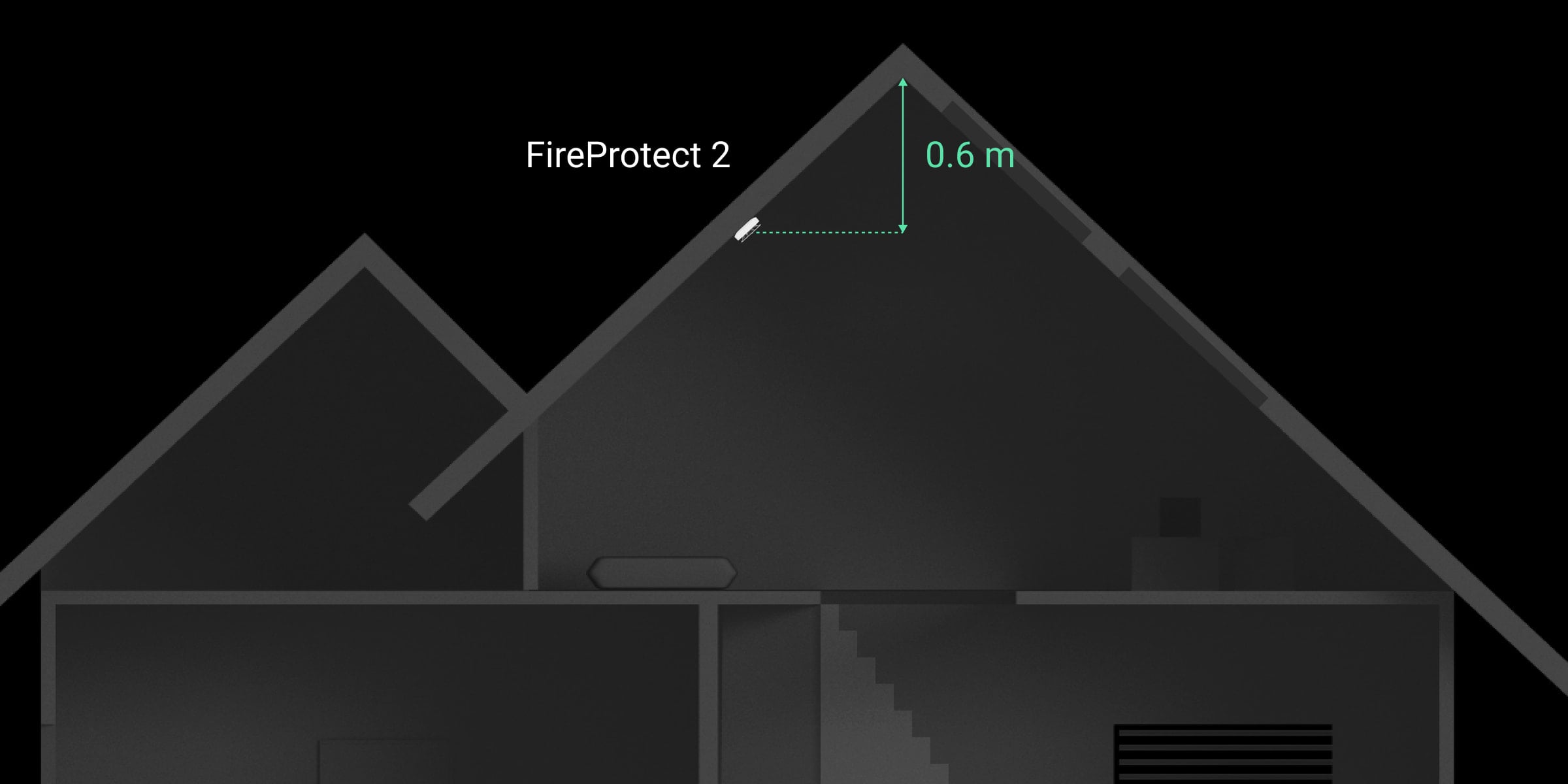
If the ceiling is sloping, the detector is installed at a distance of 60 cm from the top point of the ceiling. To select an installation place, draw a straight line down from the top of the ceiling. Then, draw a perpendicular from this line to the sloping part of the ceiling. The detector is installed at this point.
We do not recommend mounting the detector on a wall. This installation is acceptable if closely spaced beams or other obstacles interfere with the installation of the detector. Wall mounting is possible only if the detector is placed at a distance of 15–30 cm below the ceiling but above the doorways.
When installing on the wall, ensure the LEDs are visible to the user. It means FireProtect 2 must be installed upside down.
When choosing the location of the detector, consider the parameters that affect its operation:
Jeweller signal strength.
Distance between the detector and the hub.
Obstacles that affect the radio signal: walls, interfloor ceilings, big objects in the room.
Consider the placement recommendations when designing your Ajax system for the object. The security system must be designed and installed by specialists. The list of recommended Ajax partners is available here.
Signal strength
The Jeweller signal strength is determined by the ratio of the number of undelivered/corrupted data packets that are exchanged between the hub and the detector to expected ones within a certain period of time. Signal strength is indicated by the icon on the Devices
tab:
Three bars — excellent signal strength.
Two bars — good signal strength.
One bar — low signal strength; stable operation is not guaranteed.
Crossed out icon — no signal; stable operation is not guaranteed.
Check the Jeweller signal strength at the installation site. If the signal strength is as low as one or zero bars, we cannot guarantee stable operation of the device. In this case, move the device. Repositioning even by 20 cm can significantly improve the signal reception.
If, after relocation, the detector still has a low or unstable signal strength, use a radio signal range extender.
How not to install the detector
Outdoors. This can lead to the detector failure.
In places with low or unstable Jeweller signal strength. This can result in connection loss.
Inside premises with temperature and humidity outside the permissible limits. This could damage the detector.
In places with fast air circulation. For example, near fans, vents, open windows, or doors. This may interfere with Smoke/Heat and CO detection.
Opposite any objects with rapidly changing temperature. For example, electric and gas heaters. This can lead to false alarms.
In the corners of the room. This may interfere with fire detection.
In bathrooms, showers, or other areas where the temperature changes rapidly. This can lead to false alarms.
In rooms where the generation of gases/vapors/smoke is part of the operating process. For example, in a garage, where the possibility of a detector’s alarm due to vehicle exhaust gases exists. For such premises we recommend using a detector without a smoke sensor: FireProtect 2 (Heat/CO).
In very dusty places or areas with a lot of insects. Insects, dust, and other contaminants can settle on the smoke chamber lid and prevent fire detection.
Near lighting fixtures, decorations, and other interior items that may interfere with the circulation of air in the room. This may interfere with fire detection.
On surfaces that are usually warmer or colder than the rest of the room. For example, roof traps. Temperature fluctuations can interfere with fire detection.
In high or inconvenient places. Access to the Test/Mute button is required to mute the alarm and test the detector if it’s used without connection to a hub.
Installation
Make sure that you have selected the optimal installation place and it complies with the requirements of this manual.
Don’t remove the smoke chamber lid during installation. The smoke chamber lid can be removed when the enclosure is disassembled completely. The system identifies this event as a malfunction and the detector reacts with an audible signal. Users and the security company receive a malfunction notification.
During installation and operation of the Ajax security system, adhere to the rules and requirements of regulatory legal acts on electrical safety. Do not disassemble the device while it is energized or use it with a damaged power cable.
Only a competent specialist should install this device.
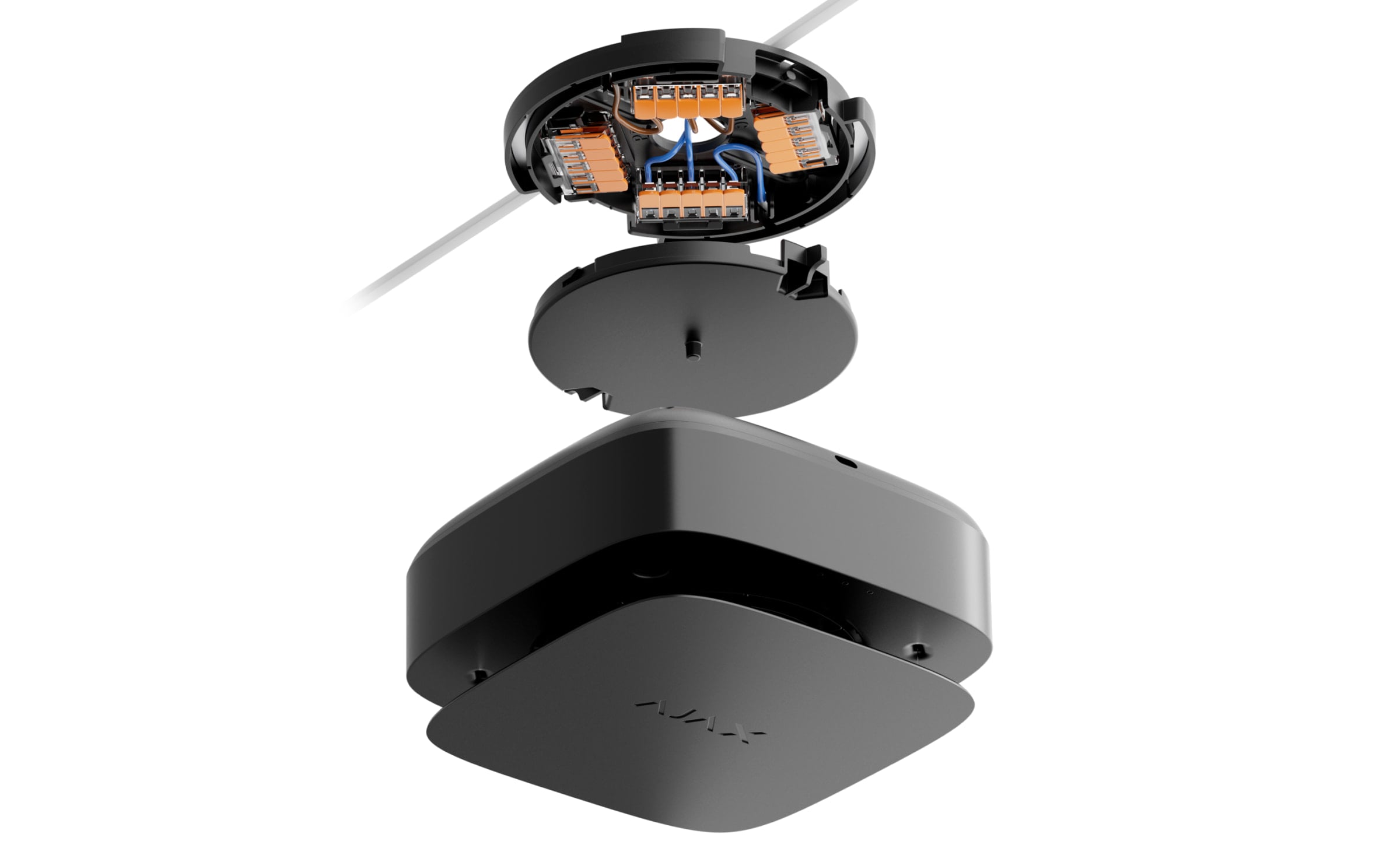
FireProtect 2 AC detectors do not require an additional surface mount pattress for installation. The detector’s mounting panel is designed for installation on any surface and includes the WAGO terminals for connecting the power cables.
The detector can be installed directly on the surface or using an accessory CableTrunk. Use CableTrunk when it is impossible to route the power cable from the back of the detector and hide it inside walls or ceiling.
CableTrunk is not included in the detector’s complete set and should be purchased separately.
To install the detector:
Remove the SmartBracket mounting panel from the detector. To remove the panel, insert a screwdriver into the appropriate hole and turn SmartBracket counterclockwise.
Fix the SmartBracket panel to a surface using temporary fasteners. Secure the detector on the SmartBracket mounting panel. To do this, turn the detector clockwise.
Run the Jeweller Signal Strength Test. The recommended value is two or three bars.
If the signal strength is a single bar or lower, we cannot guarantee the stable operation of the detector. Consider relocating the device as repositioning even by 20 cm can significantly improve the signal strength. If there is still low or unstable signal after the relocation, use a radio signal range extender.
Remove the detector from the mounting panel. Remove SmartBracket from the surface.
Remove the protective cover from the mounting panel. To do this, turn the protective cover counterclockwise as shown below.

Power off the cable that you will connect to the detector. Route the external power supply cable through the hole in the attachment panel.
Remove the WAGO terminals from the mounting panel.
Connect the wires to the appropriate WAGO terminals: power phase — to L, neutral — to N.
Secure the WAGO terminals in the mounting panel. Organize the wires and secure the protective cover.

Attach the SmartBracket panel with the bundled screws using all fixation points. When using other fasteners, make sure they do not damage or deform the mounting panel.
Place the detector on the SmartBracket mounting panel.
Adjust the position of the detector if necessary.
Turn on the external power supply.
It is necessary to perform a self-test after the installation is finished.
Actions to take in case of a fire alarm (Smoke/Heat)
NEVER IGNORE THE ALARM! Always assume the alarm is real, and evacuate from the premises immediately, even if you have doubts about the cause of the alarm signal.
Don’t open doors if you feel heat or smoke behind them. Check other exits and use an alternative escape route. Always close doors behind you when leaving.
If heavy smoke enters a room, stay close to the floor and crawl out. If possible, breathe through a wet cloth or try to hold your breath. Be aware that smoke inhalation causes more death than fire.
Evacuate as quickly as you can, don’t panic. Save time, don’t pack your things. Arrange a meeting place outside for everyone in the building. Ensure everyone has evacuated safely.
Call the fire department immediately, or ask someone nearby. Remember, even small fires can spread rapidly; call the fire department even if the alarm is automatically transmitted to a monitoring station.
NEVER come back to the house on fire.
Actions to take in case of CO alarm
Immediately open all the doors and windows to ventilate the premises if it is safe.
NEVER IGNORE THE ALARM! When you open the doors and windows for ventilation, the CO level can drop to acceptable, and the alarm may have stopped by the time help arrives. The solution to the problem may be temporary. You have to determine the CO source and make a repair.
Stop using and turn off all fuel devices where it is possible.
Evacuate from the premises leaving the doors and windows open.
WARNING: If you hear the CO alarm, it has detected dangerous levels of carbon monoxide. Always evacuate from the premises, even if you are unsure about the cause of a CO alarm.
If you have a headache and nausea, get medical help immediately. These could be the result of carbon monoxide poisoning, so tell your doctor about it.
Call your gas or other fuel supplier’s hotline. Keep the number in a noticeable place.
Avoid re-entering the premises until the alarm stops.
If the alarm was silenced by the Test/Mute button (for CO level under 300 ppm), check the CO level at the Ajax app. If it is safe to enter the premises, press the Test/Mute button again to check the CO level.
Any remote silencing feature (e.g., via Ajax app) shall only be used in the line of sight of the CO siren.
Do not use the fuel or gas appliances again until registered installers or experts have checked them.
Carbon monoxide impact
Carbon monoxide poisoning occurs regularly: many people are killed each year, and many more suffer ill health. CO is an invisible, odorless, tasteless, and extremely toxic gas. CO is produced by burning such fuels as petrol, diesel, coal, oil, natural/bottled gas, paraffin, wood, charcoal, etc. The heart and brain are rapidly damaged by oxygen starvation because red blood cells in the lungs absorb CO faster than oxygen.
The most common reasons for high levels of CO in premises:
Engines of cars, generators, etc., are left running in confined spaces (for example, a garage).
Incorrectly or poorly installed fuel-burning appliances.
Blocked or damaged vents or chimneys/flues.
The tightness of rooms where appliances for burning fuel or fireplaces are installed.
Bad ventilation in rooms with portable gas/paraffin heaters.
IMPORTANT: A CO alarm should not be used as a substitute for proper installation, use, and maintenance of fuel-burning appliances, including appropriate ventilation and exhaust systems.
The CO exposure period is also important. A low level for a long period (e.g., 150 ppm for 90 minutes) can cause the same symptoms as a high level of CO for a short period (e.g., 300 ppm CO for 30 minutes). The table below shows how different concentrations of CO affect people.
FireProtect 2 may not prevent the chronic effects of carbon monoxide exposure and will not fully protect people from the high-risk group.
CO concentration in the air, ppm | Approximate inhalation time and consequences |
35 | The maximum allowable concentration for continuous exposure in any 8-hour period (according to Occupational Safety and Health Association; OSHA). |
150 | Slight headache after 1.5 hours. |
200 | Slight headache, fatigue, dizziness, and nausea after 2–3 hours. |
400 | Frontal headaches within 1–2 hours, life-threatening after 3 hours. |
800 | Dizziness, nausea, and convulsions within 45 minutes. Unconsciousness within 2 hours. Death within 2–3 hours. |
1,600 | Headache, dizziness, and nausea within 20 minutes. Death within 1 hour. |
3,200 | Headache, dizziness, and nausea within 5–10 minutes. Death within 25-30 minutes. |
6,400 | Headache, dizziness, and nausea within 1–2 minutes. Death within 10–15 minutes. |
12,800 | Death within 1–3 minutes. |
Even if people realize they are not well, they become so disoriented by the carbon monoxide that they cannot call for help or get out of the room to save their lives. Numerous cases of carbon monoxide poisoning show that children and household pets are affected first.
Malfunctions

When a malfunction is detected, the Ajax app displays a malfunction counter on the device icon. All malfunctions are indicated in the device’s states. Fields with malfunctions will be highlighted in red.
A malfunction is displayed if:
no connection with the hub or radio signal range extender;
the detector’s enclosure is open;
low backup battery charge level;
the device service life has expired;
hardware malfunction (failure of one or more sensors of the detector).
Maintenance
The detector has a self-test system and does not require the user or installer intervention. The smoke chamber is protected from dust and insects, so there is no need to clean it. We recommend periodically running a self-test to familiarize people with the alarm sound and LED indication.
FireProtect 2 devices connected to the Ajax hubs generally do not require routine testing. All connected devices are constantly monitored for possible faults, low backup battery, and EOL signals.
However, we encourage all users to test FireProtect 2 devices periodically (monthly)* to allow residents of the building to become familiar with the fire alarm signals of the system.
*Please be aware that your local regulation might require more frequent testing (e.g., weekly).
Clean the detector enclosure of dust, cobwebs, and other contaminants as they emerge. Use a soft dry cloth suitable for equipment care. Do not use substances that contain alcohol, acetone, gasoline, and other active solvents to clean the device.
The service life of the detector is 10 years. After this period, the sensitivity of the sensors decreases. We recommend replacing the detector with a new one to ensure uninterrupted fire protection at the premises.
The detector must be changed to a new one after the backup battery is discharged.
Cautions
Avoid the situations listed in the tables below. They may affect the reliability of the CO sensor in the short or long term.
Situations that must be avoided
Situation | Possible consequences |
Contamination by alkaline metals | Significant changes to the sensor characteristics when the sensor is contaminated by alkaline metals, especially salt water spray. |
Exposure to high concentrations of common (non-acidic) gases | Exposure to high concentrations of common gases such as ammonia may cause irreversible changes. Avoid long-term exposure to or use of packing materials that may generate common gases. |
Impact of volatile organic compounds (VOCs) | Prolonged off-gassing from such VOCs may cause irreversible changes to:
Avoid packing the FireProtect 2 in a tightly closed container where VOC gases may be present. Excessive exposure to alcohol or acetone vapors the sensor may cause its temporary disability. |
Contact with water | Soaking or splashing the sensor with water may change its characteristics. |
Situations to avoid whenever possible
Situation | Possible consequences |
Exposure to silicone vapors | Sensor failure because of the exposure to silicone adhesives, hair grooming materials, or silicone rubber/putty. |
Dew condensation | The clog of gas diffusion route or deterioration of the sensing membrane. Avoid severe dew condensation that occurs for an extended period inside or on the sensor surface. |
Exposure to hydrogen sulfide or sulfuric acid gas | Sensor components corrosion, resulting in sensor damage. |
Presence of dust and oil mist | Clogging of the sensor’s internal structure caused by extremely high dust or oil mist concentrations. |
Additional cautions for installation
The sensor requires oxygen to function properly and have the characteristics described in this manual. The sensor will not operate properly in a zero-oxygen environment.
Technical specifications
All technical specifications of FireProtect 2 AC (Heat/Smoke/CO)
Warranty
Warranty for the Limited Liability Company “Ajax Systems Manufacturing” products is valid for 2 years after the date of purchase.
If you encounter any issues with the device’s functionality, we recommend contacting Ajax Technical Support first. In most cases, technical issues can be resolved remotely.
Contact Technical Support:
